The hard problems behind why the moon landing had to be faked - Part 3: Big boosters
There are great ideas undiscovered, breakthroughs available to those that can remove one of truth’s protective layers.

President Kennedy: Do you think the lunar, the manned landing on the moon is a good idea?
Webb: Yes sir, I do.
President Kennedy: Why?
Webb: Because…
President Kennedy: Could you do the same with instruments much cheaper?
Webb: No sir, you can’t do the same. The lunar landing gave us the impetus to build big boosters and to tailor them specifically for the purpose, therefore they’re going to succeed otherwise they would not have succeeded or been efficient.
Did Webb’s big boosters work? If so, why did he quit on October 7th, 1968, less than a year before man landed on the moon, using those same big boosters?
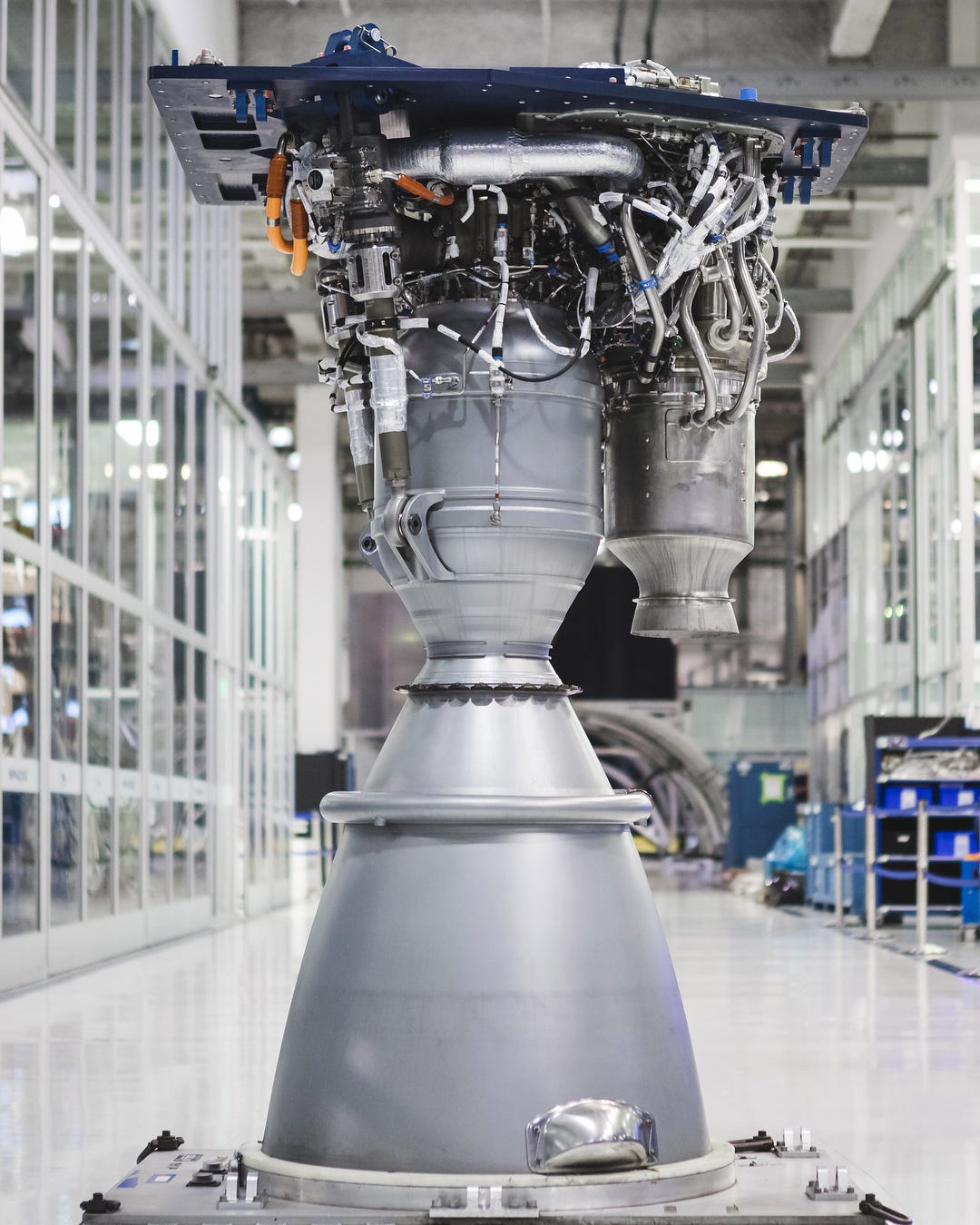
Let’s take a look at current technology. Space X’s workhorse engine is the Merlin. Like Apollo’s F1, it is an open cycle type engine that runs on RP-1 and LOX. Open cycle is a simpler design where fuel is diverted to power the fuel pumps.
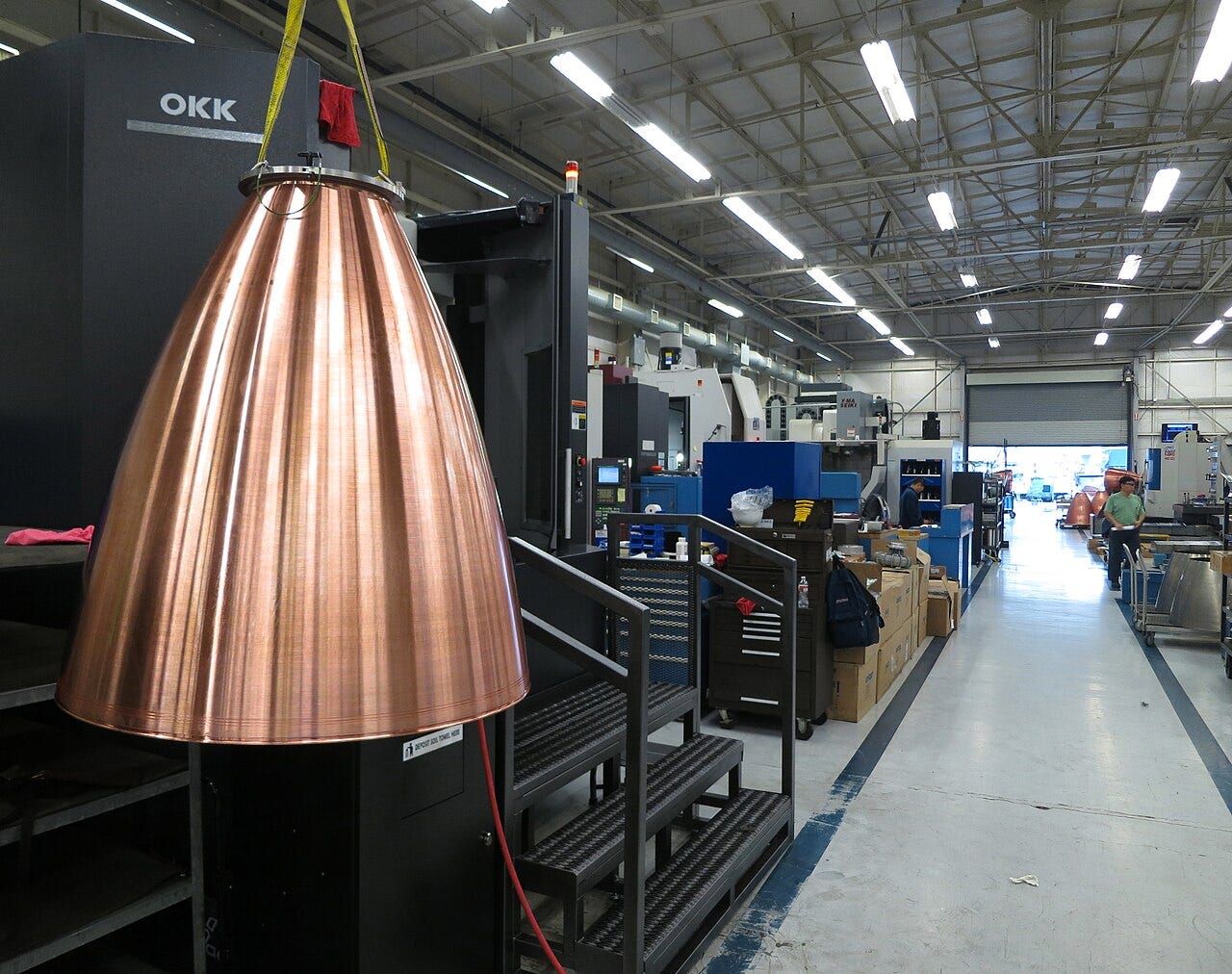
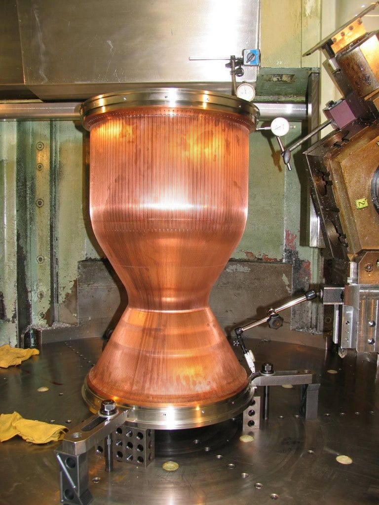
Two piece combustion chambers
From the V-2 onward, the combustion chambers of modern rockets are regeneratively cooled. This involves sending the fuel through the combustion chamber, to cool it.
The inside of the Merlin 1D’s chamber is made of molded and machined copper, the outside is stainless. The two halves are welded or brazed together. This design approach, the current best practice, originated with Aleksei Isaev in 1945 on the Soviet U-1250 engine.
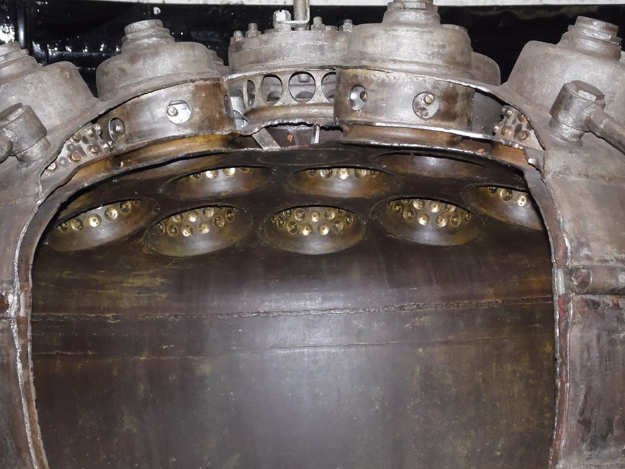
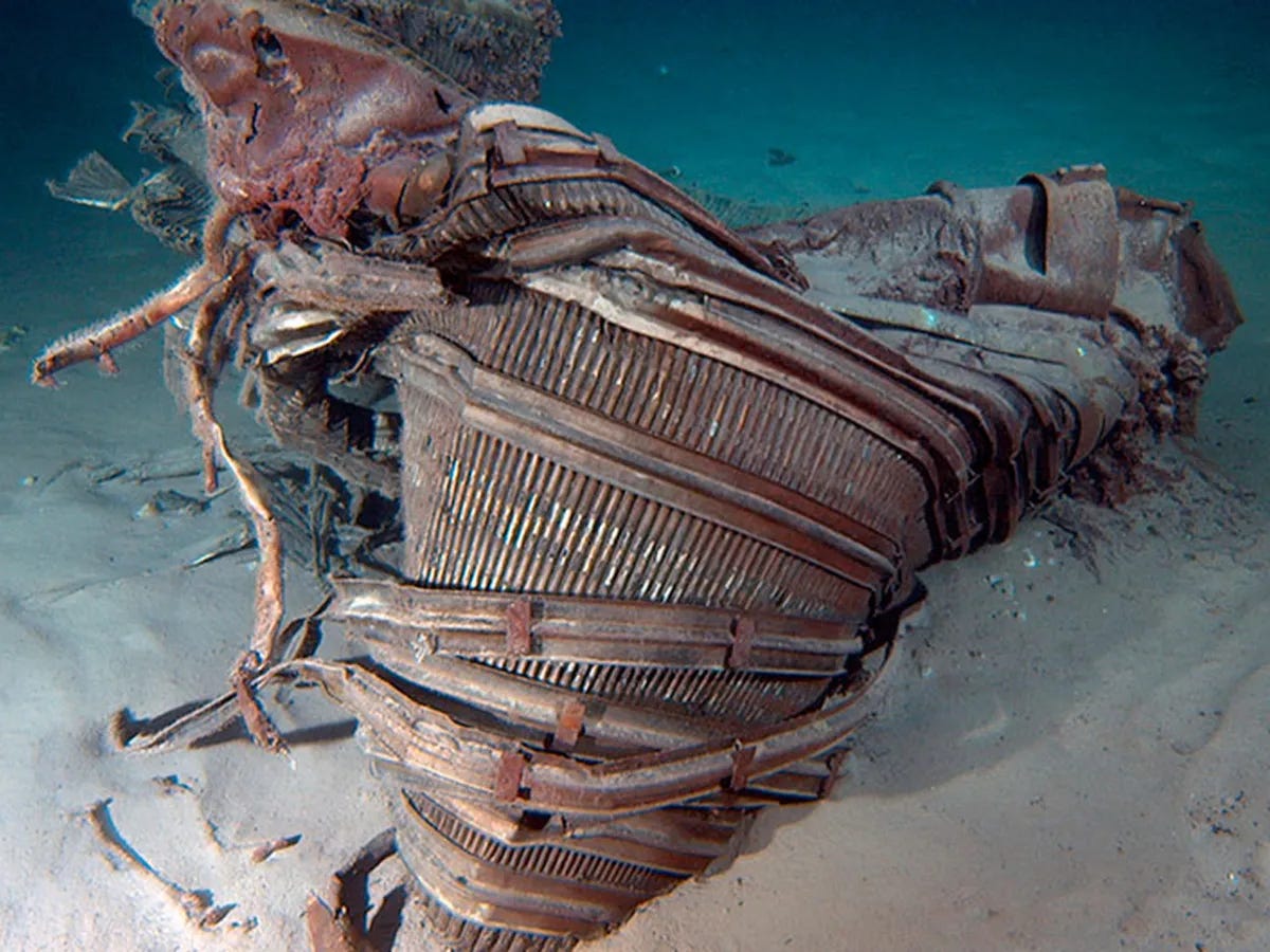
Tube bundle combustion chambers
Rocketdyne used tube bundle construction for the F1 combustion chamber. The same as on their previous rocket, the H1. Tube bundle is what it sounds like - hundreds of tubes are formed and brazed together to form a heat exchanger. The H1 used stainless tubes. The F1 used a new and exotic material, Inconel X-750, to meet its aggressive performance and weight targets. More on this later.
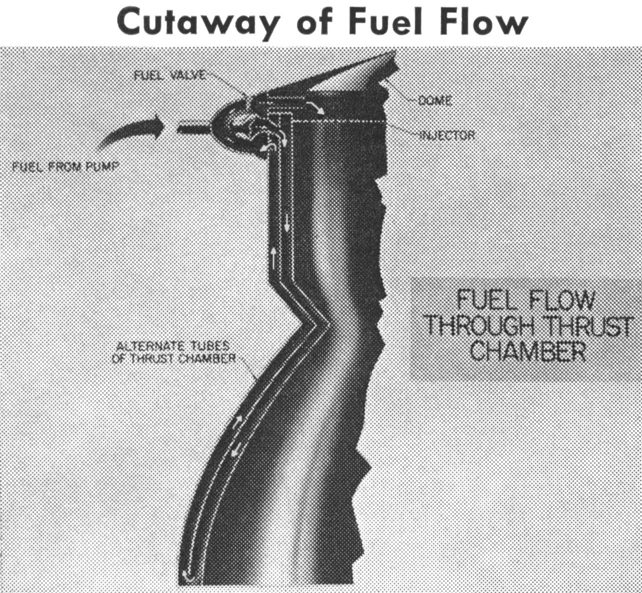
On the F1, these bifurcate (split in two) to accommodate the large expansion ratio geometry of the chamber. A single tube can’t be be stretched enough to match the expansion ratio of the chamber.
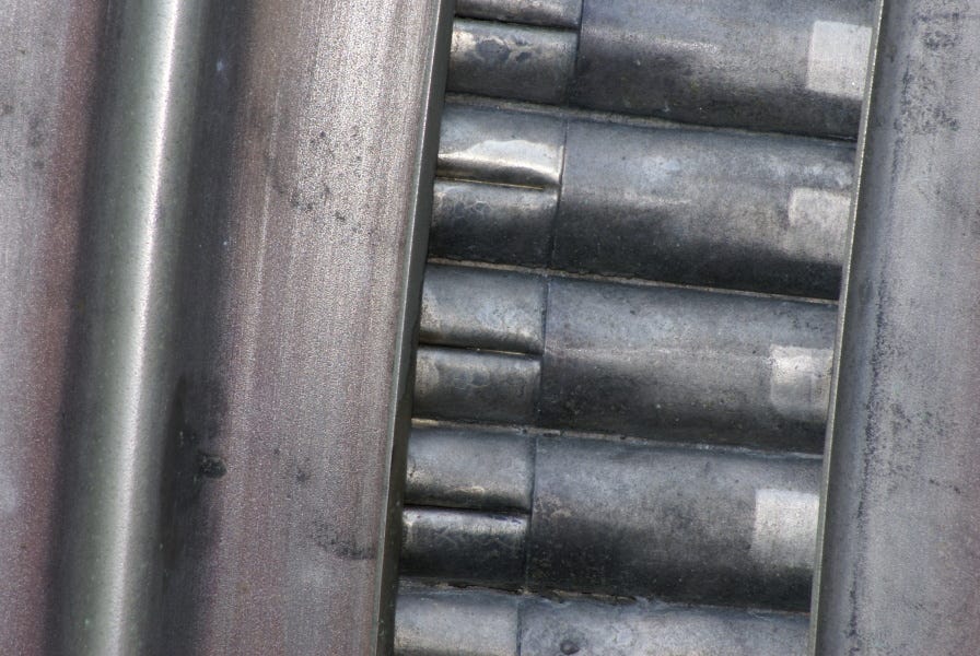
To manufacture, first sub-assemblies are brazed together, using an induction heater.

The sub-assemblies are assembled into the complete chamber and brazing alloy is sprayed on to seal the gaps between the tubes.

The whole assembly is supported by a fixture while it is in the brazing oven.

The furnace is unique in that there is no preheat, it is designed to reach temperature rapidly with the complete assembly inside. This is to avoid thermal shock to the Inconel X-750.

The second brazing operation is done upside down.

The temperature ranges of each braze alloy line up such that the second didn’t re-melt the first, and so on. The composition was silver-gold - not cheap.
Working within the 2250 to 1700 F brazing envelope, three alloys were selected: (1) Au-27Pd-22Ni-lOCr, (2) Ag-20Pd-5M11, and (3) Au-18Ni.
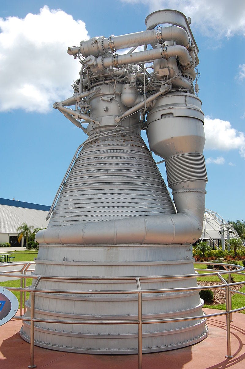
Did the F1 reach its performance goals?
To make the F1, Rocketdyne took the H1, radically upsized it, and boosted the combustion chamber pressure. The diameter of the cooling tubes increased as well. All of this puts more stress on the tube walls, which is why the material changed from stainless steel to Inconel X-750.
The walls of the tubes need to be thick enough to handle the mechanical loads, and thin enough to transfer the heat without too large of a temperature delta. They also need to present minimal resistance to the flow of rocket fuel.
Gennady Ivchenkov, Ph.D. makes the case that the F1 engine never reached its design thrust of 1,500,000 lbf, instead maxing out around 1,000,000 lbf.
His analysis shows that the safety factor of the tubes changed from a workmanlike 4.7 (H1) to a bleeding edge .9 (F1):

No big deal right? Maybe today’s engineers at NASA just don’t have the balls to turn the fuel up and let it rip like they did in the 1960s?
Speed calculation from first stage separation cloud
Stanislav Pokrovsky did a frame by frame examination of the launch footage.
According to NASA the first stage separation occurred at 2360 m/s:
The Saturn V booster recordings provide a means of verification of the performance capabilities. First stage separation occurred at the height of 65-67 km at 2360 m/s speed in the rotating Earth frame or 2750 m/s in the absolute frame.
A cloud is generated at the first stage separation. Pokrovsky compared the speed of this cloud to the speed of the 2nd stage.

While the cloud is developing and outrunning the rocket nose cone, it is moving at a speed not less than the speed of the rocket itself. Later it is slowing down to hang in still air. At the same time the velocity of the cloud lag from the rocket is increasing. The asymptotic limit of this growth is the speed of the rocket itself.

When you include the error bars, even the fastest possible speed of 1600 m/s falls short of the goal of 2360 m/s.
Thus, on the assumption that the film was shot at 24 fps, the speed calculated from the lag of the aerosol cloud is V = 1300-1520 m/s. Obviously, the range should be extended to the value of the asymptotic speed measurement error, not exceeding 100 m/s:
V = 1200-1600 m/s
Speed calculation by shock wave
Objects traveling faster than the speed of sound in atmosphere generate shock waves:

The oblique shock wave angle can be used to determine the speed of an object, for a given aerodynamic shape and atmosphere.

Once again, the maximum measured speed of 1450 m/s falls short of the goal of 2360 m/s:
For a more precise Mach number calculation of the rocket chart [6] was used. Applying the chart, a range of Mach 3.1-3.85 is obtained and the speed range is 1100-1350 m/s. (The speed of sound at the SP was approx 350m/s). It is possible that staging actually occurred at a lower height. The speed of sound in the mesosphere does not change significantly between the heights of 40-65 km. At an altitude of 50-60 km the speed of sound (see Table 1) is at maximum and equals 375 m/s, hence the range of acceptable craft speeds increases by about 100m/sec. Therefore:
V =1100-1450 m/s
Tube bundle tech is a dead end
How can a critical component in a rocket engine have a factor of safety below 1? How come measurements of actual speed don’t match the requirements for a moon mission?
If we lost the technology and it’s a difficult and painful process to bring it back, why is the new technology completely different? Why does Space X now use the two piece design on the Merlin 1D and Raptor? Why do workhorse Russian rockets that we buy, like the RD-180, also use the two piece design?
Now you see why James Webb quit. He promised a dead hero his team could solve a hard problem. They couldn’t and he quit rather than take part in the lie.
Very interesting details on this smoky story.
And the comparison with the actual rockets it’s even more interesting and clarifying.
Like your technical and pragmatical approach to those analysis! Txs a lot!
Very interesting and informative - thank you.